|
Ningbo Power Hydraulic Motor Co., Ltd.
|
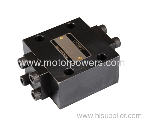
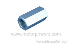
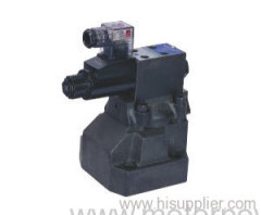
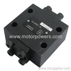
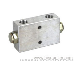
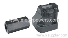
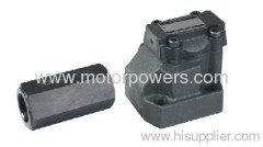
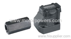
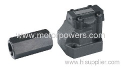
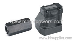
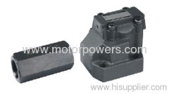
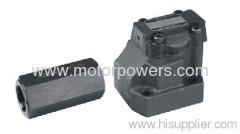
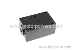
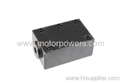
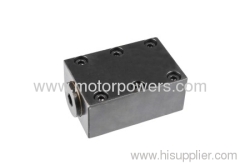
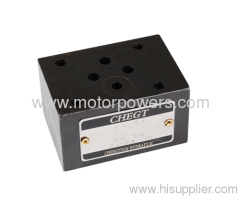
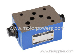
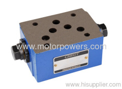
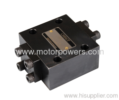
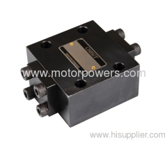
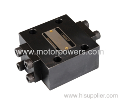
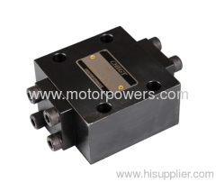
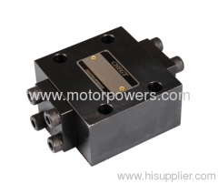
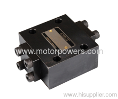
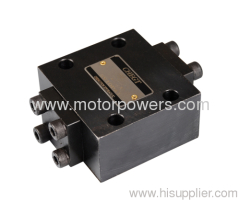
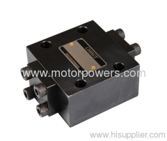
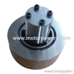
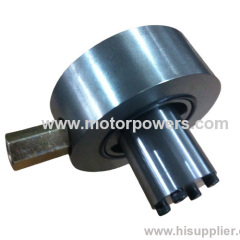
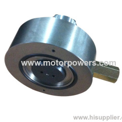
Pilot operated check valve with or without leakage port
| Payment Terms: | T/T,L/C,WU, |
| Place of Origin: | Zhejiang, China (Mainland) |
|
|
|
| Add to My Favorites | |
| HiSupplier Escrow |
Product Detail
Check valve controlled by fluid
For subplate mounting, Mounting pattern to DIN 24 340
Subplate or screw threaded connection
Features:
- Check valve controlled by fluid
- For subplate mounting, Mounting pattern to DIN 24 340
-Subplate or screw threaded connection
-With or without leakage port
-With or without pre-opening
-Type with pre-opening, dampened decompression
-3 opening pressures
Functional description, section
SV and SL valves are hydraulic pilot operated check valves in poppet type design which may be opened to allow flow in either direction.
These valves are used for the isolation of operating circuits under pressure, as safeguard against the lowering of a load when a line break occurs or against creeping movements of hydraulically locked-in actuators.
Basically these valves consist of housing (1), poppet (2), compression spring (3), control spool (4) as well as a pre-opening, as poppet valve (5), optionally.
The valve enables free flow from A to B, in the counter direction the poppet (2) is held on its seat by the system pressure, additionally to the spring force. Through the pressure connection at control port X the control piston (4) is moved to the right. This pushes the poppet (2) from the seat. Now the valve may also have a flow from B to A
In order to ensure the proper opening of the valve via the control piston(4)a certain minimum control pressure is necessary.
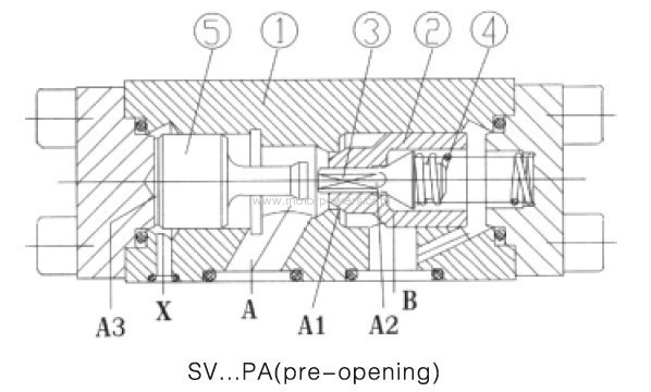
Type SV..A.. and SL..A.. (with pre-opening, section 1)
This valve has a additional pre-opening. Through pressure connection at control port X the control piston (4) is pushed to the right.
This first pushes the poppet (5) and then the poppet (2) from the seat. Now the valve may also have a flow from B to A. Because of the pre-opening there is a dampened decompression of the fluid under pressure. Through this possible pressure shocks are avoided.
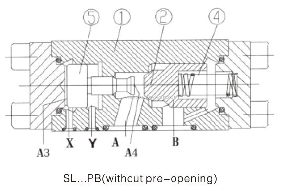
Type SL-.. (with leakage port, section 2)
The function of this valve is principally the same as the valve SV. The difference is the additional leakage port Y. With this the annulus area of the control piston (4) is separated from port A. The pressure present at port A only effects area A4 of the control piston (4).

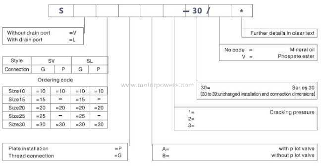
Ordering details
Technical data
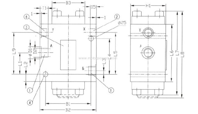
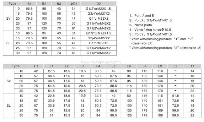
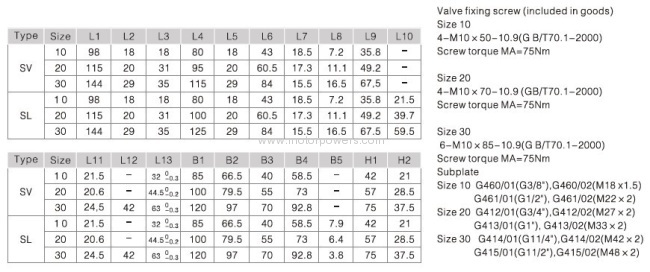
Unit Dimensions (dimensions in mm)
Threaded Connection Valve
Subplate Mounting Valve
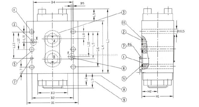
1.Ports A and B 10.O-ring
2.Port X For port A and B
3.Name plate O-ring 15×3 (Size10)
4. 4 Fixing holes with type SV/SL 20 SV/SL 10 valve O-ring 24×3 (Size10)
5. 6 fixing holes with type SV/SL 30 valve O-ring 34×3 (Size10)
6.Port Y with valve "SL" 11.For port X and Y
(with type valve "SV"this port is closed) O-ring 10×2.5 (Size10, 20, 30)
7.Fixing pin
8.Valve with cracking pressure "1"and"2"(dimension L2)
9.Valve with cracking pressure "3"(dimension L3)

- Check valve controlled by fluid
- For subplate mounting, Mounting pattern to DIN 24 340
-Subplate or screw threaded connection
-With or without leakage port
-With or without pre-opening
-Type with pre-opening, dampened decompression
-3 opening pressures
Functional description, section
SV and SL valves are hydraulic pilot operated check valves in poppet type design which may be opened to allow flow in either direction.
These valves are used for the isolation of operating circuits under pressure, as safeguard against the lowering of a load when a line break occurs or against creeping movements of hydraulically locked-in actuators.
Basically these valves consist of housing (1), poppet (2), compression spring (3), control spool (4) as well as a pre-opening, as poppet valve (5), optionally.
The valve enables free flow from A to B, in the counter direction the poppet (2) is held on its seat by the system pressure, additionally to the spring force. Through the pressure connection at control port X the control piston (4) is moved to the right. This pushes the poppet (2) from the seat. Now the valve may also have a flow from B to A
In order to ensure the proper opening of the valve via the control piston(4)a certain minimum control pressure is necessary.

Type SV..A.. and SL..A.. (with pre-opening, section 1)
This valve has a additional pre-opening. Through pressure connection at control port X the control piston (4) is pushed to the right.
This first pushes the poppet (5) and then the poppet (2) from the seat. Now the valve may also have a flow from B to A. Because of the pre-opening there is a dampened decompression of the fluid under pressure. Through this possible pressure shocks are avoided.

Type SL-.. (with leakage port, section 2)
The function of this valve is principally the same as the valve SV. The difference is the additional leakage port Y. With this the annulus area of the control piston (4) is separated from port A. The pressure present at port A only effects area A4 of the control piston (4).

Ordering details

Technical data
Type | SV10 | SL10 | SV15\20 | SL15\20 | SV25\30 | SL25\30 |
Control volume-port Y | 2.2 | 8.7 | 17.5 | |||
Control volume-port X | - | 1.9 | - | 7.7 | - | 15.8 |
Direction of flow | From A to B freely, from B to A when pilot operated | |||||
Max. operating pressure | To 31.5 | |||||
Control pressure | 0.5~31.5 | |||||
Pressure Fluid | Mineral oil or Phospate ester | |||||
Temperature range ℃ | -30~+80 | |||||
Viscosity range mm²/s | 2.8~500 | |||||
Weight kg | SV10 | SL10 | SV15\20 | SL15\20 | SV25\30 | SL25\30 |
2.5 | 4.0 | 4.5 | 8.0 | |||
Unit Dimensions (dimensions in mm)
Threaded Connection Valve


Subplate Mounting Valve

1.Ports A and B 10.O-ring
2.Port X For port A and B
3.Name plate O-ring 15×3 (Size10)
4. 4 Fixing holes with type SV/SL 20 SV/SL 10 valve O-ring 24×3 (Size10)
5. 6 fixing holes with type SV/SL 30 valve O-ring 34×3 (Size10)
6.Port Y with valve "SL" 11.For port X and Y
(with type valve "SV"this port is closed) O-ring 10×2.5 (Size10, 20, 30)
7.Fixing pin
8.Valve with cracking pressure "1"and"2"(dimension L2)
9.Valve with cracking pressure "3"(dimension L3)


Didn't find what you're looking for?
Post Buying Lead or contact
HiSupplier Customer Service Center
for help!
Related Search
Pilot Check Valve
Operated Check Valve
Hydraulic Operated Check Valve
Pilot Valve
Operated Valve
Port Valve
More>>

