|
Ningbo Power Hydraulic Motor Co., Ltd.
|
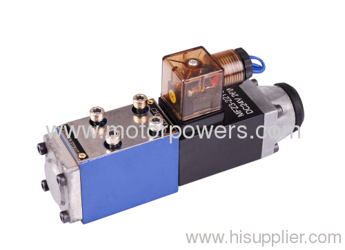
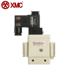
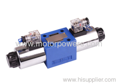
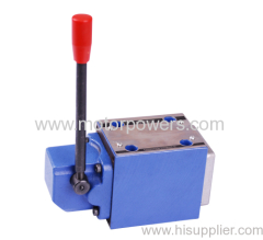
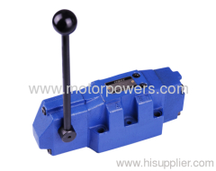
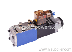
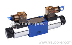
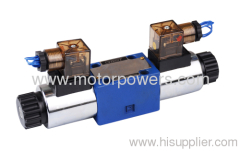
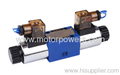
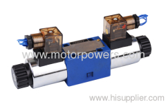
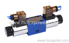
solenoid operated directional control valves
| Payment Terms: | T/T,L/C,WU, |
| Place of Origin: | Zhejiang, China (Mainland) |
|
|
|
| Add to My Favorites | |
| HiSupplier Escrow |
Product Detail
Features:
- Direct solenoid actuated directional spool valve
- Wet pin DC or /AC solenoids
Functional description, section
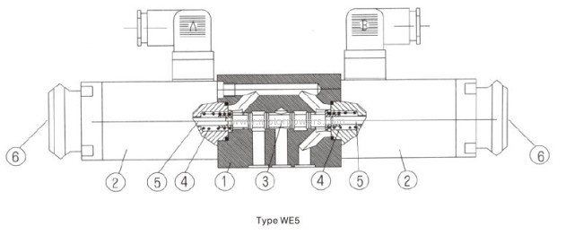
Directional valves of type WE5 are solenoid operated directional spool valves. They control the start, stop and direction of a fluid flow. These directional valves basically consist of the housing (1), one or two solenoids (2), the control spool (3), and one or two return springs(4).
The control spool (3) is held by the return spring (4) in the central or in the initial position (except for detente spools).The control spool (3) is actuated via wet pin solenoids (2), In the energized
condition. The force of the solenoid (2) acts via the plunger (5) on the control spool (3) and shifts the same from its rest position to the desired end position. Thus, the required flow pattern from P to A and B to T or P to B and A to T is selected. When the solenoid (2) is de-energized, the control spool (3) is returned to its neutral position by the return spring (4).A covered manual override is provided so that the control spool (3)can be operated without
energizing the solenoid.
Type 4WE5 N 6.OB/O...
This version is a directional valve with 2 switching positions and 2 solenoids without detent and springs. There is no defined switching position in the de-energized condition.
Type 4WE5 N 6.OB/OF...
This version is a directional valve with 2 switching potition, 2 solenoids and a detent. Thus, the relevant switching positions are fixed and continuous energization of the solenoid is not necessary.
Ordering Codes
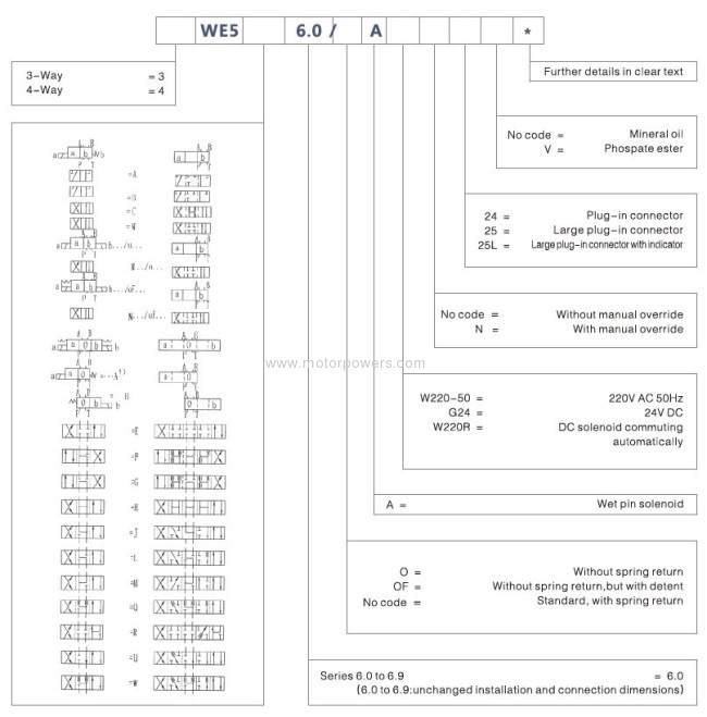
Example: Spool E with switch position "a".
Order details: ….EA…
Spool E with switch position "b".
Order details: ….EB…
*With spool types A and B port T must be used as a drain port when operating pressure exceeds 6MPa.
Technical data
Hydraulic technical data:
Pressure Fluid | Mineral oil or Phospate ester | |||
Temperature range ℃ | -30~+80 | |||
Viscosity range mm²/s | 2.8~500 | |||
Max. working pressure (Mpa) | Connection port | |||
A,B,P | T | |||
To 25 | To 6 | |||
Flow cross section (control position 0) | with symbol W | with symbol Q | ||
approx 3% of nominal cross section | approx 6% of nominal cross section | |||
Weight kg | valve | subplateG115/01 | subplateG96/01 | |
Approx1.4 | Approx0.7 | Approx0.5 | ||
Electrical technical data:
AC Voltage (V) | 110\220 in 50Hz | |
DC Voltage (V) | 12\24\110 | |
Voltage type | DC Voltage | AC Voltage |
Power requirement | 26 | |
Holding power | - | 46VA |
Making current | - | 130VA |
Duty cycle | continuous | |
Switch on time (ms) | 40 | 25 |
Switch off time (ms) | 30 | 20 |
Environment temperature ℃ | +50 | |
Coil temperature ℃ | +150 | |
Switch frequency cycles times/h | 15,000 | 7,200 |
Type of protection to DIN 40050 | IP65 | |
Switch limits:
The given operating limits are valid for the use with two flow directions (e.g. from P to A and simultaneous return flow from B to T). Due to the flow forces active inside the valves the permissible operating limit may be significantly lower if only one flow direction (from P to A and closed port B) is used. The operating limits were measured with solenoids at operating temperature, 10% under voltage and without tank back pressure.

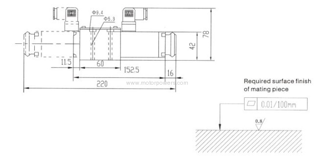
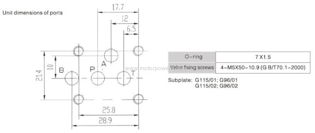
Unit dimensions (Dimensions in mm)
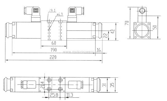
shape and connection dimensions of 2-position valve
Z4 plug-in connector

Z5 large plug-in connector

Z5L large plug-in connector with indicator

Didn't find what you're looking for?
Post Buying Lead or contact
HiSupplier Customer Service Center
for help!
Related Search
Solenoid Operated Directional Valve
Directional Valves
Directional Solenoid Valve
Hydraulic Solenoid Directional Valve
Solenoid Valves
Directional Control Valve
More>>

