|
Ningbo Power Hydraulic Motor Co., Ltd.
|
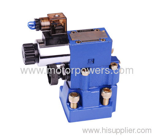
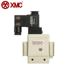
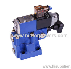
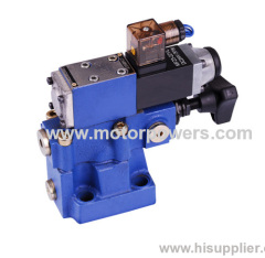
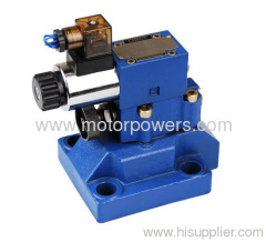
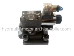
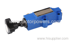
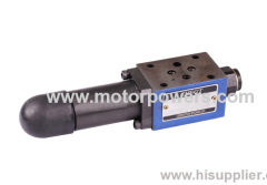
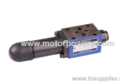
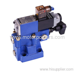
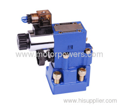
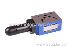
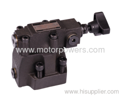
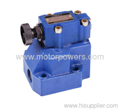
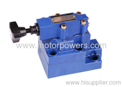
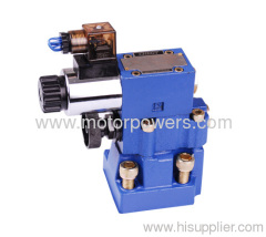
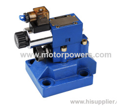
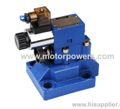
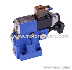
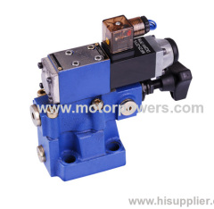
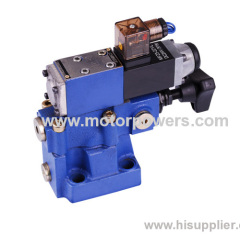
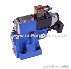
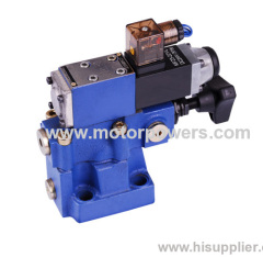
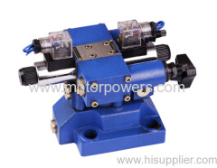
solenoid actuated pressure relief valves
| Price: | 10.0~100.0 USD |
| Place of Origin: | Zhejiang, China (Mainland) |
|
|
|
| Add to My Favorites | |
| HiSupplier Escrow |
Product Detail
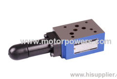
-Sandwich plate valve
- 4 pressure ranges
- 5 circuit options
-With one or two pressure relief cartridges
- 4 adjustment elements
Features of Pressure relief valve casting:
-Subplate mounting
-Pipe connection
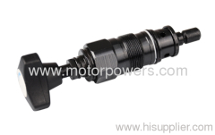
-Insert connection
-Three adjustment elements:
. Rotary knob
. Hex. head screw with protective cap
. Lockable rotary knob with scale
-Solenoid operated unloading via built-in directional spool valve
functional description of Pressure relief valve casting:
General
Types DB and DBW pressure valves are pilot operated pressure relief valves.
They are used for the limitation (DB) or limitation and solenoid actuated unloading (DBW) of the control pressure.
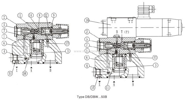
The pressure relief valves (DB) consist mainly of the main valve (1) with main spoof assembly (3) and pilot operated valve (2) with pressure adjustment element.
Pressure relief valve type DB:
The pressure present in port A acts on the main spool(3). At the same time pressure is applied via the control lines
(6) and (7), which are fitted with orifices (4) and (5), on the spring loaded side of the main spool (3) and at the ball
(8) in the pilot control valve (2). If the pressure in port A exceeds the value set at the spring (9), the ball (8) opens
against the spring (9).
The signal for this comes internally via the control lines (10) and (6) from port A. The pressure fluid on the spring
loaded side of the main spool (3) now flows via the control line (7), orifice bore (11) and ball (8) into the spring
chamber (1 2). In type DB...50B/... it flows internally via the control line (13) to tank, or in type DB..50/..Y. externally
via the control line (14). Due to the orifices (4) and (5) a pressure drop occurs at the main spool (3), the connection from port A to port B is open, Now the pressure fluid flows from port A to port B whilst maintaining the set operating pressure.
The pressure relief valve may be unloaded or switch over to a different pressure (second pressure stage) via port
"X" (15).
Pressure relief valve type DBW:
The function of this valve is basically same as the valve type DB.
The unloading at the main spool(3), however, is achieved by actuating the built-in directional valve(16).
Section of solenoid actuated pressure relief valves:
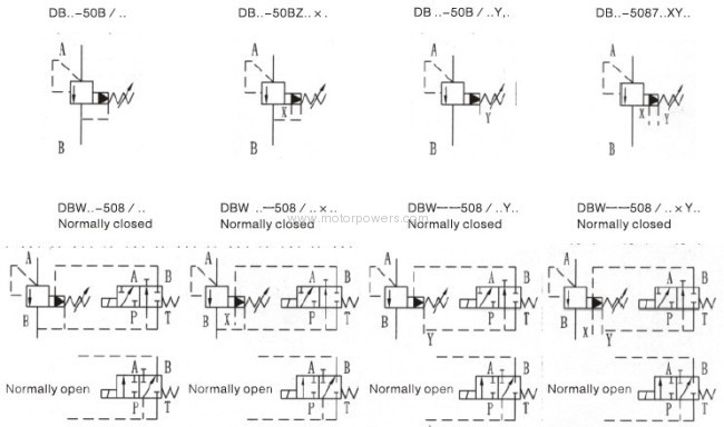
Symbol of solenoid actuated pressure relief valves:
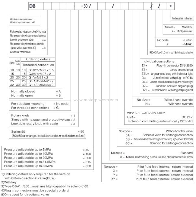
Ordering codes:
Technical data
General:
Installation position | Optional | |||||
Weight (kg) | DB 10 | DB 15 | DB 20 | DB 25 | DB 30 | |
Subplate mounting DB (kg) | 2.6 | - | 3.5 | - | 4.4 | |
DBW (kg) | 3.8 | - | 4.7 | - | 5.6 | |
DBC (kg) | 1.2 (DBWC add 1.2kg) | |||||
DBC 10 or 30 (kg) | 1.5 (DBWC 10 or 30 add 1.2kg) | |||||
Cartridge connection DB…G…(kg) | 5.3 | 5.2 | 5.1 | 5.0 | 4.8 | |
DBW…G… (kg) | 6.5 | 6.4 | 6.3 | 6.2 | 6.0 | |
Technical data for the directional valves | See WE6 | |||||
Hydraulic data:
Operating pressure port A B X (Mpa) | To 35.0 | |||||
Back pressure Port Y | DB (Mpa) | To 31.5 | ||||
DBW.6A.(standard solenoids ) (Mpa) | DC: 10.0 AC: 16.0 | |||||
DBW.6B.(Min.setting pressure) (Mpa) | DC/AV:16.0 | |||||
Indicator light (Mpa) | Flow dependent | |||||
Maximum (Mpa) | To 5.0, 10.0, 20.0, 31.5, 35.0 | |||||
Max. flow -Subplate mounting L/min -Threaded connection L/min | DB 10 | DB 15 | DB 20 | DB 25 | DB 30 | |
250 | - | 500 | - | 650 | ||
250 | 500 | 500 | 500 | 650 | ||
Pressure Fluid | Mineral oil or Phospate ester | |||||
Temperature range ℃ | -30~+80 | |||||
Viscosity range mm²/s | 10~800 | |||||
Filtration | NAS1638 9 class | |||||
Unit dimensions (dimensions in mm)
Subplate mounting:
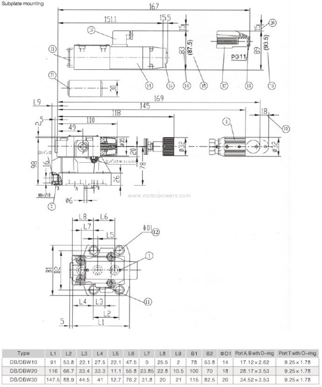
Threaded connection
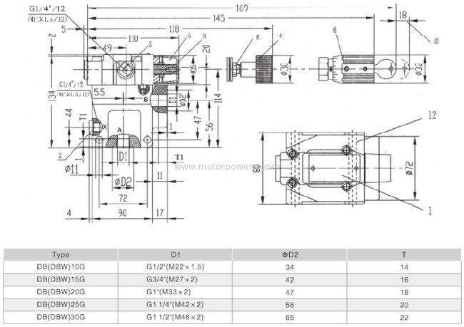
Cartridge connection
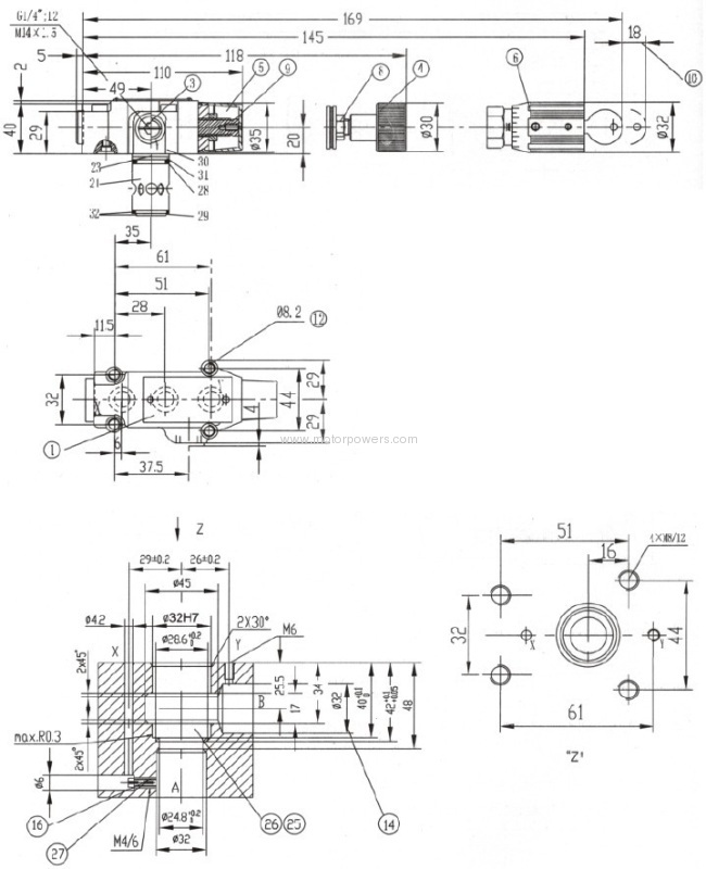
Didn't find what you're looking for?
Post Buying Lead or contact
HiSupplier Customer Service Center
for help!
Related Search
Pressure Relief
Solenoid Valves
Pressure Relief Valve
Pilot Solenoid Valves
Miniature Solenoid Valves
Plastic Solenoid Valves
More>>

