|
Ningbo Power Hydraulic Motor Co., Ltd.
|
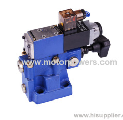
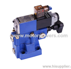
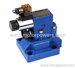
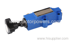
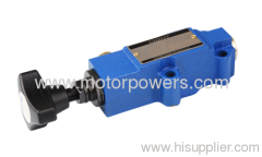
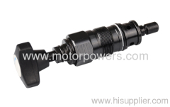
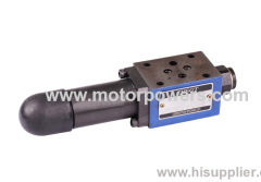
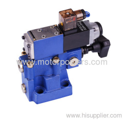
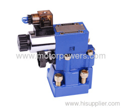
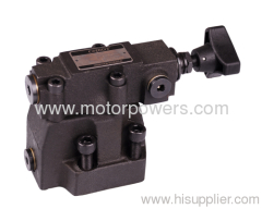
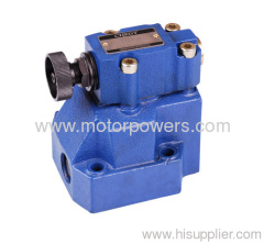
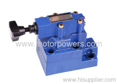
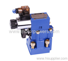
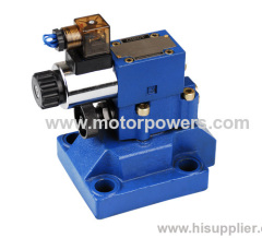
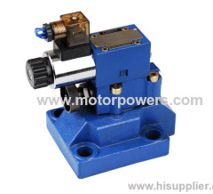
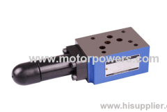
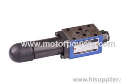
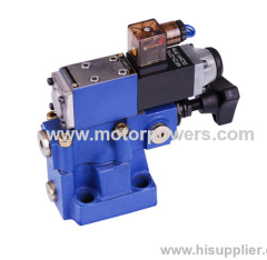
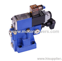
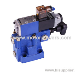
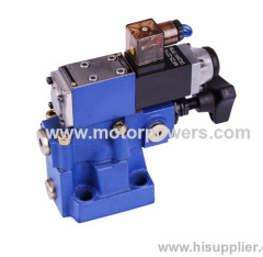
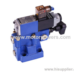
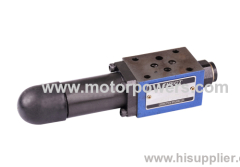
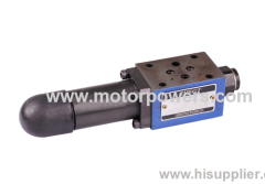
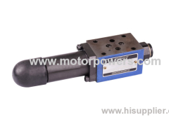
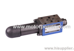
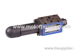
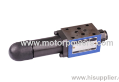
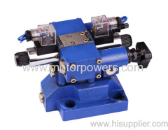
7.8kg pilot operated pressure shut-off valves
| Price: | 10.0~100.0 USD |
| Place of Origin: | Zhejiang, China (Mainland) |
|
|
|
| Add to My Favorites | |
| HiSupplier Escrow |
Product Detail
Features:
. Lockable rotary knob with scale
. Rotary knob with scale
- 4 pressure ratings, optional
- Solenoid actuated unloading
Functional description
Pressure control valves type DA/DAW are pilot operated pressure shut-off valves.
They are used to switch a pump flow over to unpressurised by-pass as soon as the accumulator loading pressure is reached. Further applications for the valve are in systems that have high and low pressure pumps. In this case the low pressure pump is switched to unpressurised by-pass as soon as the set high pressure is reached.
Pressure shut-off valves basically consist of the main valve with the main spool assembly, pilot valve with pressure adjustment element and check valve. In size 10 valves, the check valve is built into the main valve. In valve sizes 25 and 32 the check valve is built into a separate plate installed under the main
Pressure shut-off valve type DA
Diverting pump flow from P to A to P to T.
The pump delivers flow via check valve (1) into the hydraulic system (P to A). Pressure in port A acts via pilot line (3) on the pilot control spool (4). At the same time, pressure in port P passes via orifices (5) and (7) to the spring loaded side of the main spool (6) and ball (8) in the pilot valve (2). As soon as the set cut-off pressure in the hydraulic system is reached, the ball (8) lifts off against spring (9). Pressure fluid now flows via orifices (5) and (7) into spring chamber (11). From here, the fluid is returned to tank either internally via control line in valve type DA..50B/... or externally via control line in valve type DA..50B/..Y... Due to orifices (5) and (7), a pressure drop is now present at the main spool (6). The main spool (6) now lifts off its seat and opens the connection from P to T. The check valve (1) now closes the connection from A to P. The ball (8) is now held open by the system pressure via pilot spool (4).
Diverting pump flow from P to T to P to A.
The area of the pilot spool (4) is 1O % or optionally 17 % greater :than the effective area of the ball (8). The effective force on the pilot spool (4) is, therefore, 1O or 17 % greater than the effective force on the ball (8). when the actuator pressure falls in relation to the cut-off pressure by a value which corresponds to the switching pressure differential, spring (9) pushes ball (8) on to its seat. Pressure is then built up on the spring loaded side of the main spool (6). In conjunction with spring (10), this closes the main spool (6) and isolates the connection
from P to T. The pump flow passes once more via the check valve (1) into the hydraulic system (P to A).
Pressure cut-off valve type DAW
The function of this valve is basically the same as the DA valve. A solenoid actuated directional valve (12) can, however switch the set cut-off pressure which is under the pilot valve (2) either from P to T or from P to A.
Section of DA10...50B
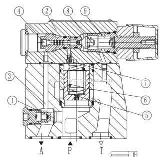
Section of DAW20,30...50B

Features:
- For subplate mounting:
- 4 adjustment elements:
. Rotary knob
. Sleeve with internal hexagon and protective cap
. Lockable rotary knob with scale
. Rotary knob with scale
- 4 pressure ratings, optional
The connection between the DA valve and the hydraulic accumulator should be as possible and with a low pressure drop. With high pump flows as well as small switch differentials (10%) then preferable the "Y" version should be used.
Circuit example of pilot operated pressure shut-off valves:
Hydraulic system with accumulator
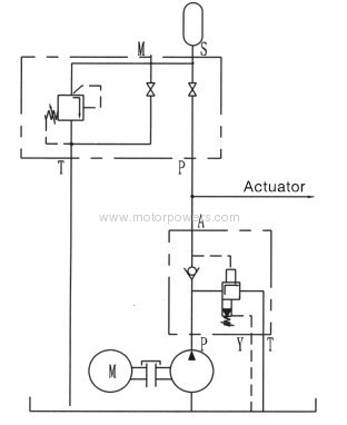
Circuit example of pilot operated pressure shut-off valves:
Hydraulic system with accumulator

Hydraulic system with high and low pressure pumps
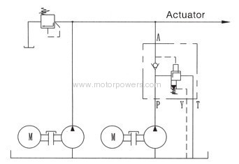
For the high pump flow rate or low differential pressure, type Y is best.
Ordering codes:

Technical data:
Size | 10 | 20 | 30 | |
Max. flow L/min (the switching pressure table) | 10% | 40 | 80 | 120 |
17% | 60 | 120 | 240 | |
Operating pressure port A (Mpa) | To 31.5 | |||
Max. settable pressure (Mpa) | to 5, to 10, to 20, to 31.5 | |||
Pressure Fluid | Mineral oil or Phospate ester | |||
Viscosity range mm²/s | 10~800 | |||
Temperature range ℃ | -30~+80 | |||
Filtration | Max. permissible Degree of fluid contamination is to NAS 1638, class 9β10≥75 | |||
Weight (kg) | DA | 2.6 | 6.6 | 12.3 |
DAW | 3.8 | 7.8 | 13.5 | |
DAC | 1.2 (DAW add to 1.2kg) | |||
DAC30 | 1.5 (DAWC 30 add to 1.2kg) | |||
Directional valve characteristic | See WE5 | |||
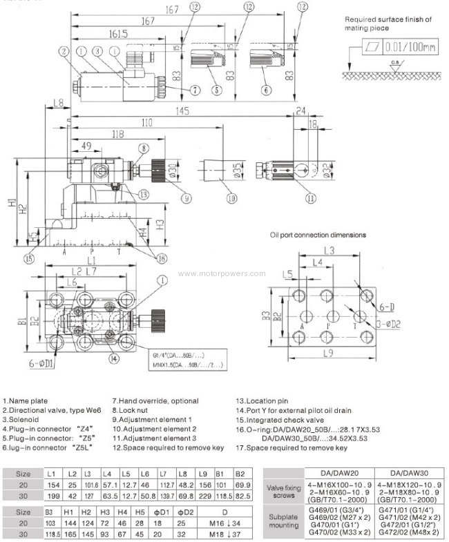
Unit dimensions (dimensions in mm)
Size 10
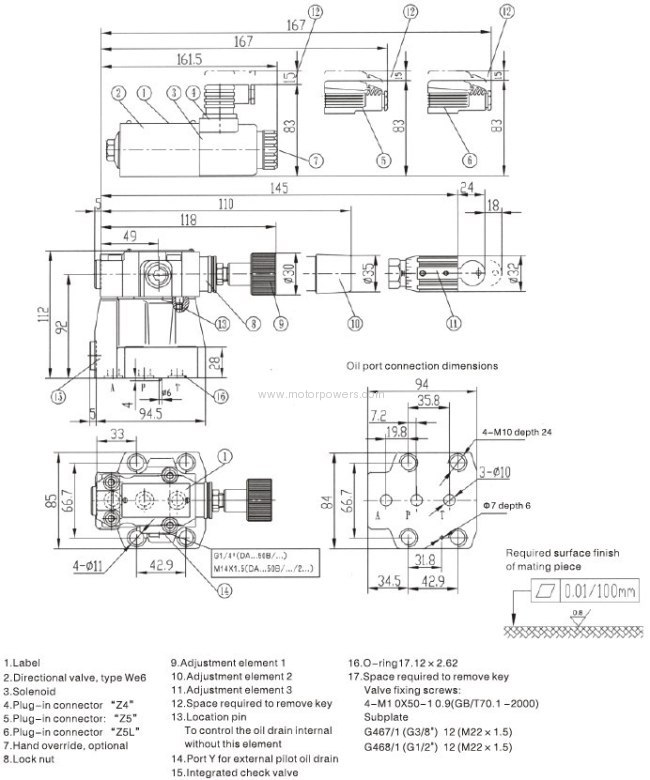
Size 20, 30
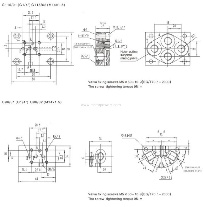
Subplate 1 (dimensions in mm)

Subplate 2 (dimensions in mm)
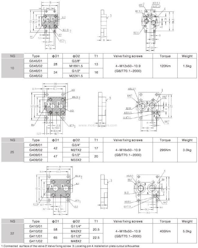
Subplate 3 (dimensions in mm)
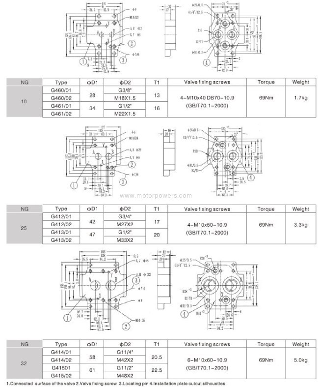
Subplate 4 (dimensions in mm)
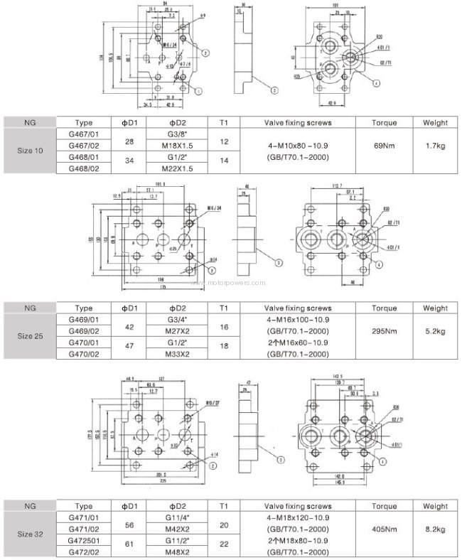
Subplate 5 (dimensions in mm)
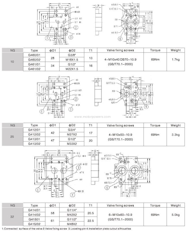
Subplate 6 (dimensions in mm)
Didn't find what you're looking for?
Post Buying Lead or contact
HiSupplier Customer Service Center
for help!
Related Search
Shut Off Valve
Gas Shut Off Valve
Shut Off Shower
Pilot Solenoid Valves
Hand Operated Valves
Pressure Operated Valve
More>>


